As a MWIR Camera Module Manufacturer, Hope-Wish understands that long-range camera selection is not just a resolution decision. Engineering teams need to confirm that a target will produce enough pixels at the required distance, while procurement teams need comparable specifications, credible test evidence, integration details, and a realistic total cost. This guide brings those decisions into a practical step-by-step process.
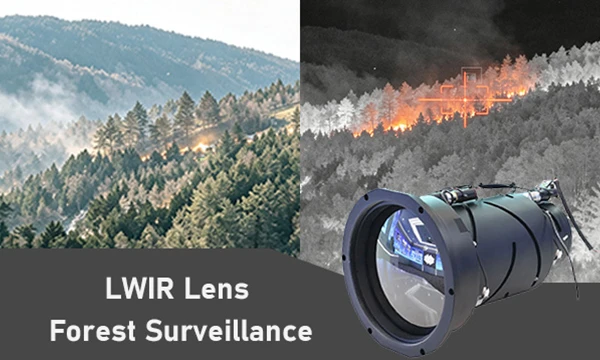
People searching for an MWIR camera module for long-range imaging generally need a way to compare camera performance in a real scene, not just a list of detector specifications. The key questions are whether the target can be detected or identified at the required range, whether the lens and sensor provide enough detail, and whether the module can work with the planned platform and environment. Use the steps below to turn those questions into measurable requirements.
1. Define the mission before comparing camera modules
Step 1: Write down the target, distance, and decision the camera must support
Start with the operational requirement. State what the camera must observe, at what distance, under which conditions, and what an operator or automated system must decide from the image. Detection, recognition, and identification are different tasks. Detection means noticing that an object is present; recognition means distinguishing its general type; identification means resolving enough detail to tell it apart from similar objects. Do not treat these outcomes as interchangeable.
- Target: describe its approximate width or height, shape, and thermal contrast against the background.
- Range: specify the minimum and maximum operating distances, not just a best-case demonstration distance.
- Scene: record expected backgrounds, terrain, sky conditions, humidity, haze, and likely obstructions.
- Use case: specify whether the system supports human viewing, tracking, measurement, or automated analytics.
- Performance: define the required detection, recognition, or identification probability and the conditions under which it must be met.
- Platform: note whether the camera is fixed, handheld, vehicle-mounted, airborne, or part of a stabilized payload.
For purchasing teams, these details prevent a common dispute: engineering may evaluate image quality while procurement compares price and nominal resolution. A shared mission statement gives both groups the same basis for evaluating offers.
2. Calculate the pixels on target at the required range
Step 2: Estimate angular pixel size and target coverage
Use detector pixel pitch and lens focal length to estimate the camera's instantaneous field of view. For small angles, the approximate angular pixel size in radians is pixel pitch divided by focal length. The approximate number of pixels across a target is target dimension divided by the product of range and angular pixel size. Use consistent units throughout the calculation.
- Record the target dimension that matters for the task, such as the width of a vehicle or person.
- Convert target dimension, range, pixel pitch, and focal length into consistent units.
- Calculate angular pixel size: IFOV in radians is approximately pixel pitch divided by focal length.
- Calculate pixels across the target: target dimension divided by range multiplied by IFOV.
- Repeat the calculation for the farthest required distance and for the smallest relevant target dimension.
- Compare the result with a suitable task criterion, then confirm it with representative imagery or a field test.
This calculation is a screening tool, not a guarantee of usable range. Atmospheric attenuation, target-to-background contrast, focus, motion, detector noise, image processing, and optical quality all affect the result. Detection and identification criteria such as Johnson-style criteria can help frame an initial estimate, but they rely on assumptions and should not replace testing under the intended conditions.
Check whether the field of view fits the search and tracking task
A narrow field of view can put more pixels on a distant target, but it also makes searching and tracking harder. A wider field of view covers more scene area but gives the target fewer pixels. Decide whether the system needs a single fixed view, a zoom or multiple lenses, or a wider search camera paired with a narrow identification camera. Confirm that the required field of view is available at the focal length used in the pixel calculation.
3. Choose detector specifications that support the mission
Step 3: Compare resolution, pixel pitch, frame rate, and sensitivity together
Do not select a detector by resolution alone. The detector, optics, processing, and operating conditions work as a system. A higher pixel count may help provide more scene coverage or target detail, but it can also affect data rate, power use, processing requirements, and cost.
- Resolution: check horizontal and vertical pixel counts against the required field of view and image-processing workload.
- Pixel pitch: consider how it changes angular sampling for a given focal length and how it fits the optical design.
- Frame rate: match the rate to target speed, platform motion, tracking needs, and display or recording limits.
- NETD: use noise-equivalent temperature difference as one sensitivity indicator, but compare measurement conditions and test methods before ranking modules.
- Dynamic range: check whether the module can handle the expected range of scene temperatures without losing useful detail.
- Image processing: ask about non-uniformity correction, bad-pixel handling, image enhancement, and access to raw or processed output.
- Cooling: determine whether the module is cooled or uncooled and review warm-up time, power, service needs, operating life, and performance requirements.
Ask suppliers to state how performance figures were measured. A specification without test conditions may not predict performance in your scene. Request representative images or test data that use the proposed detector, lens, processing settings, and operating temperature.
4. Match the lens to range, field of view, and image quality
Step 4: Select focal length, aperture, and focus range as a system
The lens determines how much of the scene reaches the detector and how many pixels cover the target. Use the pixel-on-target estimate to choose a starting focal length, then verify the resulting field of view and optical performance. Confirm that the supplier's quoted range is based on the lens configuration you will actually buy.
- Focal length: a longer focal length generally narrows the field of view and increases target sampling at a given detector pixel pitch.
- F-number and aperture: a lower f-number can collect more infrared energy, but optical size, cost, focus tolerance, and depth of field also matter.
- Lens transmission: check transmission across the module's MWIR spectral band and across the full optical path.
- Focus: confirm manual, motorized, fixed, or continuous focus options and the distances over which focus is required.
- Image quality: request information about modulation transfer function, distortion, vignetting, and performance across the detector field.
- Zoom: verify whether zoom is continuous or stepped, whether focus is maintained, and whether the stated field-of-view limits are achievable.
- Protection: specify window material, coatings, sealing, and any environmental or sacrificial window requirements.
A module with a suitable detector can still underperform if the lens is mismatched, poorly focused, or not designed for the required spectral band. Compare complete camera and lens configurations rather than comparing detector data sheets in isolation.
5. Confirm environmental and system integration requirements
Step 5: Check interfaces, power, size, and operating conditions
Before choosing a preferred module, check that it can be installed and operated in the planned system. Integration issues discovered after purchase can cause redesigns, schedule delays, and additional costs.
- Mechanical: confirm dimensions, mass, mounting points, optical axis, center of gravity, and clearance for connectors and cabling.
- Electrical: verify input voltage, peak and average power, startup behavior, grounding, and power connector details.
- Data: confirm video format, output resolution, frame rate, interface type, latency, and compatibility with the host processor or display.
- Control: check command protocols, software development kit availability, lens control, temperature reporting, and integration documentation.
- Thermal: determine heat dissipation, allowable case temperature, warm-up time, and any cooling or ventilation needs.
- Environment: specify operating and storage temperature, humidity, shock, vibration, ingress protection, and altitude requirements.
- Compliance: identify any required safety, export, regulatory, or customer-specific documentation before placing an order.
Ask the supplier for an interface control document and confirm the exact hardware and firmware configuration in the quotation. If the module will operate on a moving platform, include platform vibration, stabilization, motion blur, and line-of-sight performance in the review.
6. Evaluate suppliers using evidence and a fair comparison
Step 6: Request comparable data from each MWIR camera module supplier
Build a comparison sheet that separates guaranteed specifications from typical values and estimates. Require every supplier to quote the same target use case, lens, field of view, operating temperature, and interface wherever possible. This makes differences easier to interpret and reduces the risk of comparing unlike configurations.
- Request a complete configuration list, including detector, lens, firmware, accessories, cables, and software.
- Ask for test images or recorded data from a representative range and scene, with test conditions clearly stated.
- Request performance data for the intended task, not only a general maximum detection distance.
- Confirm manufacturing lead time, product lifecycle status, repair process, warranty, and technical support availability.
- Ask whether specifications are guaranteed, typical, or dependent on optional components.
- Review how the supplier handles calibration, acceptance testing, documentation, and configuration changes.
- Check whether the supplier can support integration questions and provide the required interface documentation.
A long-range claim is meaningful only when its target size, atmospheric conditions, lens, detector, image processing, and success criterion are disclosed. Treat unsupported range statements as claims to verify rather than as guaranteed system performance.
7. Run a sample evaluation before committing to production
Step 7: Test the proposed configuration against acceptance criteria
When practical, evaluate a sample or demonstration system before a production order. Agree on the test method in advance so that engineering, procurement, and the supplier interpret the result consistently.
- Write acceptance criteria for image quality, field of view, target task, frame rate, interfaces, and environmental behavior.
- Use the proposed detector, lens, firmware, processing settings, and mounting arrangement.
- Test at representative short, medium, and maximum operating ranges where access and safety allow.
- Include realistic backgrounds, target orientations, day and night conditions, and relevant weather conditions.
- Record focus, camera settings, distance, target dimensions, ambient conditions, and any processing applied.
- Have intended operators assess whether the image supports the required decision, not merely whether it looks sharp.
- Document pass or fail results and resolve differences before approving the production configuration.
Account for lifecycle cost as well as purchase price. Include integration engineering, optics, mounting, power, cooling, software, training, maintenance, calibration, spares, and expected service requirements in the procurement comparison.
8. Use the right tools and avoid common selection mistakes
Tools to prepare before requesting quotations
These tools help turn a general requirement into a reviewable specification. They can be simple documents or spreadsheet templates; the important point is to use consistent assumptions.
- Mission requirements worksheet covering target, range, task, scene, platform, and environment.
- Spreadsheet for pixel-on-target, IFOV, field-of-view, power, and cost comparisons.
- Lens and detector data sheets that identify the exact configuration and measurement conditions.
- Range and target test plan with acceptance criteria and a method to record observations.
- Integration checklist for mechanical, electrical, data, software, and thermal interfaces.
- Supplier comparison matrix separating guaranteed specifications, typical values, options, lead time, and support.
- Representative sample scene or recorded reference data for evaluating image usability.
Common mistakes to avoid
- Choosing by detector resolution alone without calculating target pixels at the required distance.
- Assuming a published maximum range guarantees detection or identification in all weather and backgrounds.
- Comparing NETD, frame rate, or range figures without checking test conditions and camera configuration.
- Selecting a long focal length without checking search coverage, tracking difficulty, or platform movement.
- Ignoring lens transmission, focus behavior, optical quality, or the difference between detector and system performance.
- Overlooking power, heat, interfaces, firmware, mounting, and environmental limits until after selection.
- Failing to define acceptance criteria before a sample evaluation or field demonstration.
- Comparing purchase prices while leaving integration, support, maintenance, and lifecycle costs out of the decision.
The best choice is the complete MWIR camera and lens configuration that meets the operational task with verified evidence and can be integrated within the project's technical and commercial limits. Hope-Wish can help engineering and procurement teams review application requirements, compare module configurations, and plan a practical evaluation. Contact a MWIR Camera Module Manufacturer such as Hope-Wish with your target size, distance, field of view, environment, and interface needs to begin a specification-based selection.